
Surface profile is the blast-produced anchor pattern on steel, measured as the average peak-to-valley height and expressed in mils (thousandths of an inch) or micrometers (µm). Before any blasting begins, you need three things locked into your project documents: a numeric profile range, the specific measurement method (ASTM D4417 Method A, B, or C, or NACE SP0287-2016), and a sampling plan.
Two actions to take right now:
- Select the correct replica tape grade (Coarse or X-Coarse) for your expected profile range before the crew starts blasting.
- Document every reading, the method used, the tape grade, and the operator’s name on a traceable inspection record.
Pro Tip: Never let “visual inspection only” stand as the acceptance criterion on a contract. Call a numeric method and a profile range in the spec, or you have no enforceable standard.
Key Takeaways
Correct surface profile, specified with a numeric range and a named ASTM or NACE method, is the single most controllable variable in industrial coating adhesion and long-term performance.
| Point | Details |
|---|---|
| Define profile precisely | Specify peak-to-valley height in mils and µm using Rz-style measurement, not Ra. |
| Name the method in the spec | Call ASTM D4417 Method C or NACE SP0287-2016 by number; different methods produce different readings. |
| Match tape grade to range | Use Coarse tape for 0.8–2.5 mils; X-Coarse for 1.5–4.5 mils per SSPC-PA 17. |
| Sample adequately | Take a minimum of five readings per 100 ft²; average must fall within the acceptance range. |
| Southernsandblastingandpainting | Performs replica-tape verification per ASTM/NACE standards and provides traceable inspection records on every project. |
Table of Contents
- What “surface profile” actually means for blast-prepared steel
- Why surface profile controls coating adhesion and longevity
- Standards to cite and how to write them into a project spec
- How each field measurement method works — and where each one falls short
- How to write profile requirements and sampling plans that hold up in the field
- Common field errors and the QA/QC checklist that prevents them
- What a surface profile measurement report must contain
- Health, safety, and environmental considerations for blasting and measurement
- How Southernsandblastingandpainting controls and verifies profile on every project
- Why getting profile right the first time is the most cost-effective decision you can make
- Southern Sandblasting & Painting delivers verified profile on every project
- Sources
What “surface profile” actually means for blast-prepared steel
Surface profile, also called anchor pattern or anchor profile, is the microgeometry created when abrasive media strikes and deforms a steel surface. The measurement value used in coating specifications is the average of the maximum peak-to-valley heights across a sampled area, which corresponds to the Rz-style parameter rather than the arithmetic mean roughness (Ra) that general profilometers often report by default.
That distinction matters in practice. Ra averages all deviations from the mean line, which smooths out the extreme peaks and valleys that actually govern how a coating locks in. Rz captures those extremes. Mixing the two in a specification creates measurement confusion and disputes on acceptance, as Elcometer’s technical guidance makes clear.
Acceptable units and notation for specifications:
- Mils (1 mil = 25.4 µm): standard in U.S. project documents
- Micrometers (µm): required when referencing ISO 8503 comparators
- Recommended notation: “1.5–3.0 mils (38–76 µm) per ASTM D4417 Method C”
Why surface profile controls coating adhesion and longevity
Adhesion to bare steel is primarily mechanical, not chemical. The anchor pattern increases the true contact area between the steel and the applied coating, and the peaks and valleys physically interlock with the cured film. A clean, flat surface with no profile gives a coating almost nothing to grip.
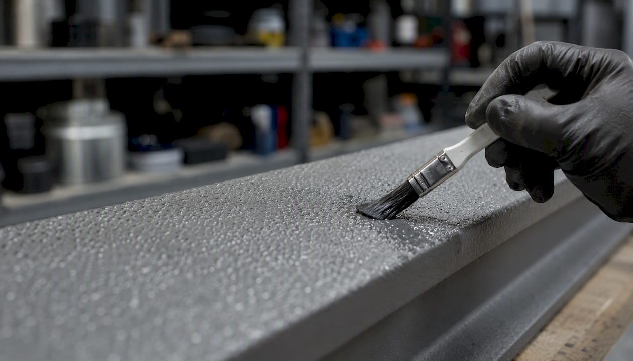
Too little profile produces poor mechanical anchoring and early delamination, particularly under cyclic thermal or mechanical stress. Too much profile creates a different set of problems: peaks that stand proud of the applied coating’s dry film thickness (DFT), leading to pinholing, rust-through at the tips, and higher paint consumption because the valleys consume more material than a flat surface would. Industry anchor-pattern guides warn specifically about over-profiling increasing paint consumption and causing rust-through at the peaks.
The profile becomes the decisive parameter when:
- The coating system is thin-film (under 4 mils DFT), where peak exposure is a real risk
- The substrate will be exposed to immersion or high-humidity service
- A zinc-rich primer is specified, since zinc relies on direct metal contact for galvanic protection
Pro Tip: When specifying DFT, account for the profile depth. A 3-mil profile in a 5-mil DFT spec means the valleys may receive only 2 mils of coating. Adjust your minimum DFT requirement accordingly, or specify DFT measured from the peaks.
Standards to cite and how to write them into a project spec
The four standards every U.S. specifier needs to know:
- ASTM D4417 (Methods A, B, and C): the primary U.S. standard for field measurement of surface profile. Method A uses visual comparators; Method B uses a depth micrometer; Method C uses replica tape with a spring micrometer.
- NACE SP0287-2016: governs the replica tape procedure specifically, with round-robin test appendices that document the technique’s accuracy and repeatability in field conditions.
- ISO 8503 series (Parts 1, 5, and 12): covers surface roughness comparators (Part 1), replica tape (Part 5), and stylus instruments (Part 12). Use when a project references international standards or involves ISO-specified coating systems.
- SSPC-PA 17: provides practical process-control guidance on tape grade selection, micrometer zeroing, minimum sample areas, and blast-cleaning verification procedures.
Sample spec language you can adapt:
“Provide a surface profile of 1.5–3.0 mils (38–76 µm), measured per ASTM D4417 Method C (replica tape, Coarse grade) with a minimum of five readings per 100 ft² of prepared surface. Record individual readings, the mean, and the tape grade on the inspection form. Profile outside this range requires re-blast and re-measurement before coating application.”
For heavy-duty epoxy or thermal spray, shift the range upward: 2.5–4.0 mils (63–102 µm), X-Coarse tape, same sampling density. KTA’s guidance reinforces calling a specific ASTM or NACE method by number, because different methods sample different areas and can produce different readings on the same surface.
Pro Tip: Specify both the tape grade AND the method number. A spec that says “measure per ASTM D4417” without naming Method C leaves the contractor free to use a depth micrometer, which typically reads lower and may pass a surface that would fail under tape.
How each field measurement method works — and where each one falls short
ASTM D4417 defines three methods; ASTM D7127 covers portable stylus instruments.
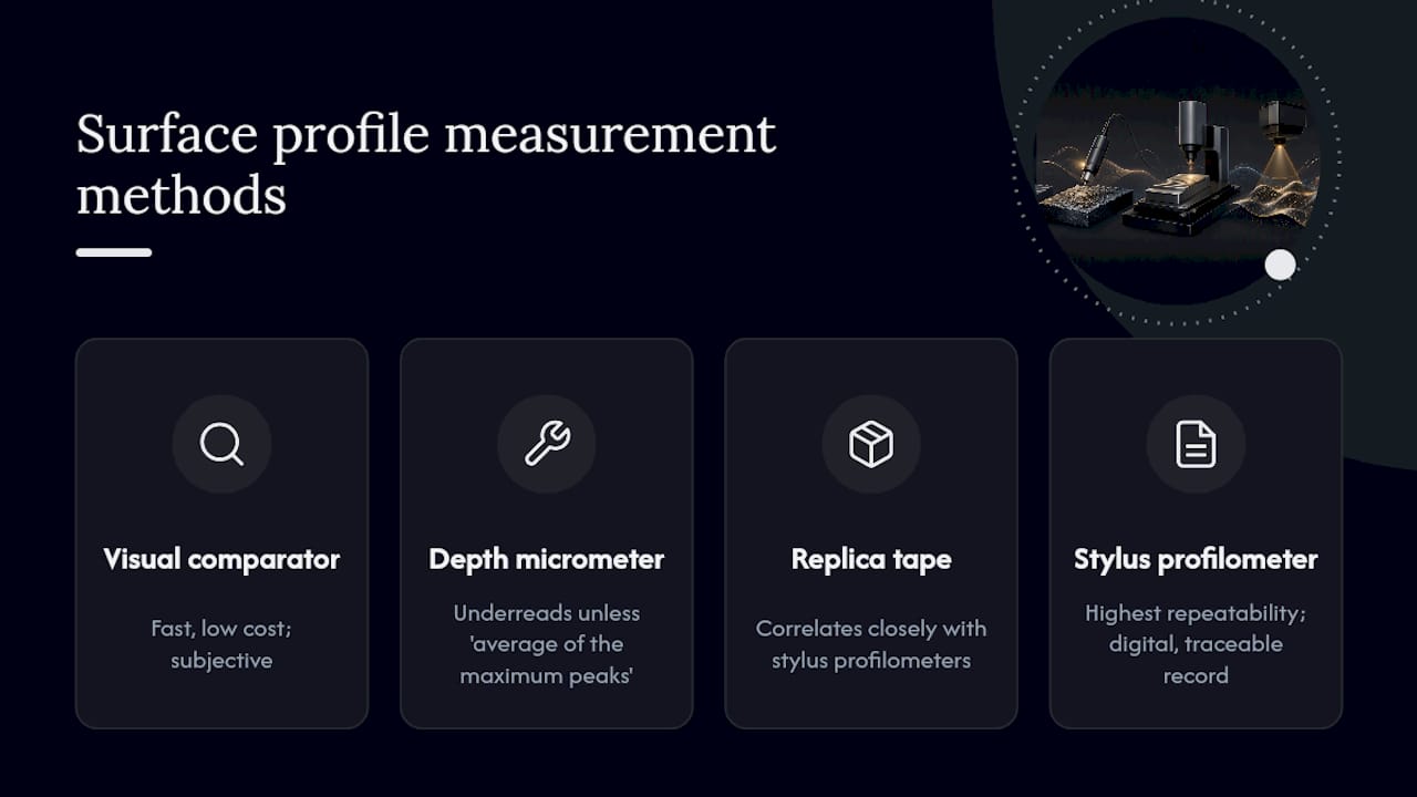
Method A — Visual comparators (ISO 8503-1): The inspector compares the blasted surface to a set of reference coupons under raking light. Fast and inexpensive, but subjective. Acceptable for process monitoring; not recommended as the sole acceptance method on critical work.
Method B — Depth micrometer: A flat-footed micrometer measures the distance from the highest peak to the base plane. Portable and low cost, but it consistently reads lower than tape or stylus unless the operator applies the “average of the maximum peaks” analysis. A comparative study by DeFelsko found that depth micrometers correlate with other methods only when that specific analysis approach is used.
Method C — Replica tape (NACE SP0287-2016): Burnishing a Testex Press-O-Film tape onto the surface creates a negative impression of the profile. The compressed foam thickness, measured with a spring micrometer and corrected by subtracting the tape’s base thickness (2 mils for Coarse, 1.5 mils for X-Coarse), gives the profile reading. Replica tape correlates closely with stylus profilometers across their overlapping ranges.
Portable stylus profilometer (ASTM D7127): Drags a diamond-tipped stylus across the surface and reports Rz electronically. Highest repeatability and produces a digital, traceable record. More expensive than tape and requires a clean, dry surface.
*Correlates only with “average of the maximum peaks” analysis.
Pro Tip: On acceptance disputes, the stylus profilometer is the tiebreaker. Its digital record and high repeatability make it the closest field equivalent to a laboratory microscope measurement.
How to write profile requirements and sampling plans that hold up in the field
Spec language that survives a dispute names the method, the tape grade, the numeric range, and the sampling density. Here is a checklist for building a complete profile requirement:
- State the numeric range in mils and µm (e.g., 1.5–3.0 mils / 38–76 µm)
- Name the measurement method and standard (ASTM D4417 Method C, NACE SP0287-2016)
- Specify the tape grade: Coarse (0.8–2.5 mils) or X-Coarse (1.5–4.5 mils)
- Set sampling density: minimum five readings per 100 ft² or per discrete structural component
- Define the averaging rule: the mean of all readings at a location must fall within the acceptance range; no single reading may fall outside a stated tolerance band
- Identify who records and signs the inspection form
For blasting profile requirements by coating family:
- Thin-film epoxy or alkyd (DFT under 4 mils): 1.0–2.0 mils, Coarse tape
- Heavy-duty epoxy or polyurethane: 1.5–3.0 mils, Coarse or X-Coarse
- Zinc-rich primer: 2.0–3.5 mils, X-Coarse
- Thermal spray (TSA/TSZ): 2.5–4.0 mils, X-Coarse
Field measurement guides recommend measuring after blasting and dust removal, taking readings at multiple locations, and using the tape grade matched to the expected profile range.
Pro Tip: Specify that readings be taken at least 6 inches from welds and edges. Profile near welds is often irregular and will skew your average if included in the acceptance sample.
Common field errors and the QA/QC checklist that prevents them
The mistakes that generate the most disputes:
- Using Coarse tape on a surface profiled above 2.5 mils (the tape bottoms out and reads falsely low)
- Inconsistent burnishing pressure, which compresses the foam unevenly
- Measuring over weld spatter or mill scale remnants
- Taking only two or three readings and calling it a sample
- Failing to zero the micrometer on a flat reference surface before each set of readings
QA/QC checklist for field verification:
- Zero the spring micrometer on a flat glass plate before each measurement session.
- Confirm the tape grade matches the expected profile range per SSPC-PA 17.
- Blow down the surface with clean, dry air; remove all dust and loose abrasive before taping.
- Burnish with a smooth, rounded tool (a burnishing stylus or the back of a pen cap) using firm, consistent circular pressure until the tape surface shows a uniform matte texture.
- Measure the compressed tape immediately; foam relaxes over time.
- Take a minimum of five readings per location; discard any reading taken within 6 inches of a weld.
- Record the mean and range; flag any location where the mean falls outside the acceptance window.
- If a location fails, re-blast that area, re-clean, and re-measure before proceeding.
Pro Tip: After any process change — abrasive type, nozzle pressure, standoff distance — take a new set of readings immediately. Don’t assume the profile held.
What a surface profile measurement report must contain
A complete report supports acceptance, protects both parties in a dispute, and links to the broader coating QA record. Mandatory fields:
- Project name, location, and date
- Substrate type and blast standard achieved (e.g., SSPC-SP 10 Near-White)
- Measurement method and standard (ASTM D4417 Method C)
- Tape grade and instrument model/serial number
- Operator name and certification level
- Ambient conditions at time of measurement (temperature, relative humidity, dew point)
- Individual readings, mean, and range per location
- Acceptance statement (pass/fail against spec range)
Archive the profile report alongside the DFT records and coating application logs. Inspectors and owners who can pull a complete chain of documentation — profile, DFT, batch numbers, application conditions — have a defensible record if a coating failure claim arises years later.
Health, safety, and environmental considerations for blasting and measurement
Abrasive blasting generates respirable dust and, depending on the substrate, may release lead, chromate, or other hazardous compounds. Required PPE for blasting operations includes a supplied-air respirator (NIOSH-approved), blast hood, hearing protection, and cut-resistant gloves. Inspectors performing close-contact measurements in or near an active blast zone need at minimum an N95 respirator, safety glasses, and hearing protection.
Environmental conditions that invalidate profile readings:
- Wet or damp surfaces (condensation, rain): moisture compresses the tape foam and inflates readings
- Embedded abrasive: creates false peaks; blow down and brush before measuring
- Salt contamination: does not affect the reading directly, but a surface that passes profile and fails a conductivity test still requires re-blast
Abrasive waste containment is governed by federal EPA regulations and state-level rules that vary by jurisdiction. Spent abrasive containing lead paint debris is typically classified as hazardous waste under RCRA and requires licensed disposal. Containment structures (tarps, shrouding, vacuum blasting) are standard on bridge and infrastructure work where runoff control is mandatory.
Statistic callout: OSHA’s permissible exposure limit (PEL) for silica dust is 50 µg/m³ as an 8-hour time-weighted average — a threshold that conventional dry abrasive blasting can exceed by a significant margin without proper engineering controls and respiratory protection.
How Southernsandblastingandpainting controls and verifies profile on every project
Southernsandblastingandpainting’s field workflow follows a structured sequence that aligns with ASTM D4417, NACE SP0287-2016, and SSPC-PA 17 requirements:
- Pre-job sample area: Before full production blasting, blast a representative test area and measure profile with replica tape to confirm abrasive type, grit size, pressure, and standoff distance produce the specified range.
- Abrasive and pressure selection: Match media type and grit to the target profile range, referencing the role of blasting media types in achieving consistent anchor patterns.
- Replica tape verification: Coarse or X-Coarse Testex tape, spring micrometer zeroed on glass, minimum five readings per location, recorded on a project-specific inspection form.
- Documented acceptance: Each location is logged with individual readings, mean, tape grade, operator, and ambient conditions before coating application is authorized.
- Corrective re-blast: Any location with a mean outside the spec range is re-blasted and re-measured; no coating is applied until the location passes.
With over 20 years of experience on water tanks, bridges, pipelines, and municipal infrastructure across Central Florida, Southernsandblastingandpainting treats profile verification as a non-optional step, not a formality.
Pro Tip: Ask your contractor for the profile inspection forms before coating application begins. If they can’t produce them, the profile was not formally verified.
Why getting profile right the first time is the most cost-effective decision you can make
The coating industry’s lifecycle cost argument for correct profile is straightforward: a coating system that fails prematurely because of inadequate profile requires full removal, re-blast, and reapplication, which typically costs more than the original job. Corrosion repairs on structural steel or water infrastructure add engineering costs, downtime, and potential regulatory exposure on top of that.
There is also a subtler financial argument around DFT. When profile depth is not accounted for in the DFT specification, the valleys consume coating material that never shows up in a peak-measurement DFT reading. The result is a system that appears to meet spec but is actually under-film in the valleys, exactly where corrosion initiates. Correct profile specification, paired with a DFT requirement that accounts for valley depth, closes that gap. The paint adhesion and asset protection case is straightforward: the cost of a proper profile verification program is a fraction of one premature coating failure on a major asset.
Southern Sandblasting & Painting delivers verified profile on every project
Getting profile right requires more than a blasting crew and a tape measure. It requires a contractor who understands the standards, selects the right abrasive for the target range, and documents every reading before a drop of coating goes on.
Southernsandblastingandpainting brings 20+ years of industrial surface preparation experience to commercial, municipal, and infrastructure projects across Central Florida. The team performs replica-tape profile verification per ASTM D4417 and NACE SP0287-2016, delivers traceable inspection records, and re-blasts any location that falls outside spec before coating begins. From sandblasting services in Orlando to full-cycle QA/QC reporting on large municipal contracts, the process is built around the standards your spec requires. Contact Southernsandblastingandpainting to request a site survey or project consultation.
Sources
- Understanding Surface Profile — Elcometer
- Surface profile: a comparison of measurement methods — DeFelsko
- NACE SP0287-2016: Surface Profile Measurement
- Measuring coating surface profile — KTA
- How to Measure Surface Profile Accurately (Field Methods Compared) – QCSQCI – QA/QC Inspection Guides
- SSPC-PA 17-2012: Process Control Guidance


